INSTALLATION
To install the EH2100/EH2100P perform the following steps:
1. Determine the location and direction of the enclosure.
HARD CEILING - Cut an opening in the ceiling. Avoid cutting into the ceiling support
structure (rafters and joists).
SUSPENDED CEILING -The E2100 rotating mounting plate may be used when installing
the EH2100/EH2100P into a suspended ceiling. To install the
E2100 follow the instructions supplied with the mounting plate.
2. Open the cover of the enclosure to expose the mounting holes in the flange.
3. Remove the appropriate knockouts (EH2100 only) needed for camera power and video
wiring. The EH2100P must have feedthrough holes drilled in needed locations.
4. Insert the enclosure into the opening and secure with the appropriate fasteners. The
EH2100P fasteners must meet plenum standards.
5. Mount the camera and lens onto the adjustable mounting bracket. Adjust the position of the
camera and lens to clear the enclosure cover when closed. Tighten the mounting bracket
fasteners.
6. Route the appropriate cables into the enclosure. Make all necessary electrical connections.
Refer to Table A for the type of video coaxial cable to use. Refer to Table B for 24 VAC wir-
ing distances.
7. Close and lock the cover.
NOTE:
Flange extenders have
been supplied to support the en-
closure if adequate mounting
support is not available.
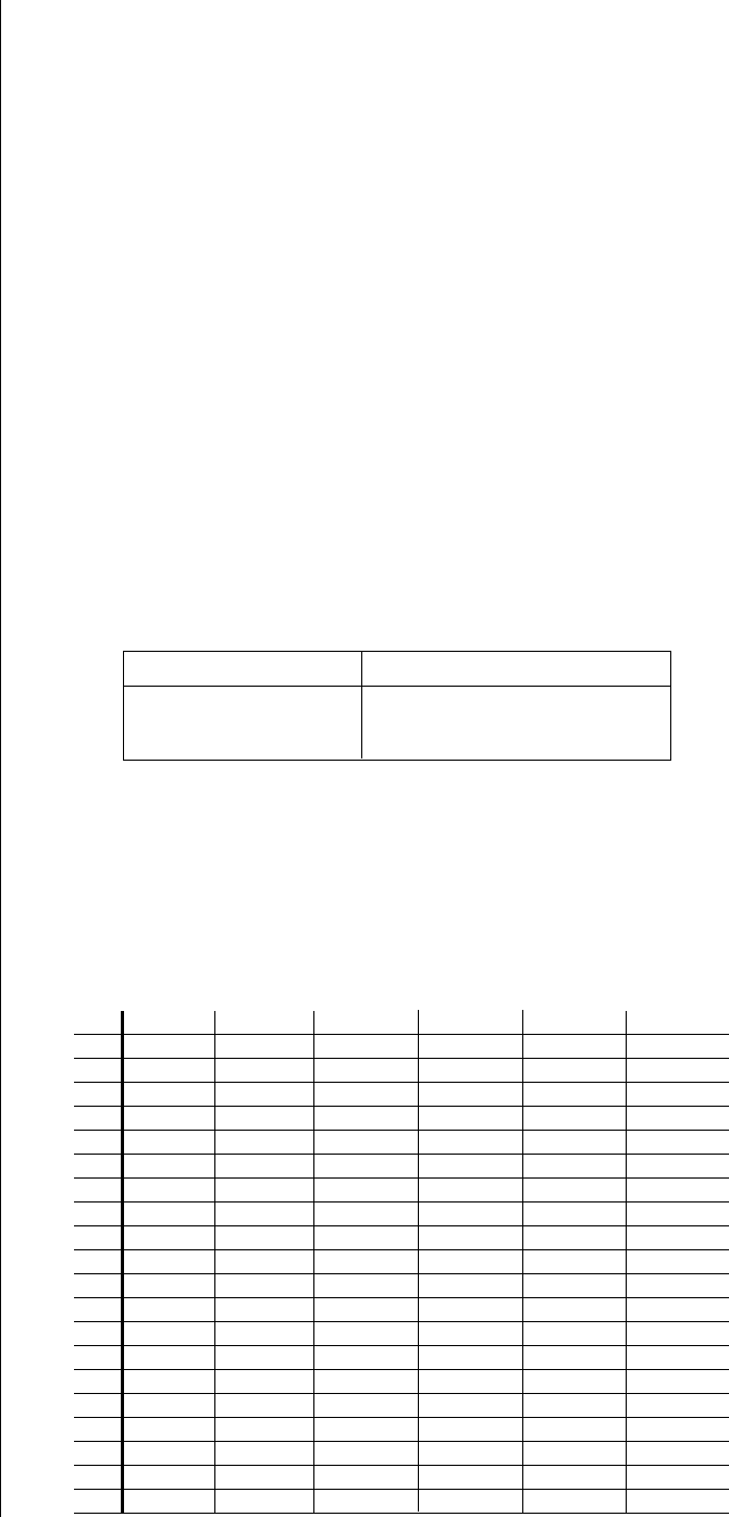
Table A. Video Coaxial Cable Requirements
Cable Type* Maximum Distance
RG59/U 750 ft (229 m)
RG6/U 1,000 ft (305 m)
RG11/U 1,500 ft (457 m)
* Minimum cable requirements:
75 ohms impedance
All-copper center conductor
All-copper braided shield with 95% braid coverage
EXAMPLE:
An enclosure that
requires 80 vA and is installed 35
feet (10 m) from the transformer
would require a minimum wire
gauge of 20 Awg.
NOTE:
Distances are calculated
in feet; values in parentheses are
meters.
20 18 16 14 12 10
10 283 (86) 451 (137) 716 (218) 1,142 (348) 1,811 (551) 2,880 (877)
20 141 (42) 225 (68) 358 (109) 571 (174) 905 (275) 1,440 (438)
30 94 (28) 150 (45) 238 (72) 380 (115) 603 (183) 960 (292)
40 70 (21) 112 (34) 179 (54) 285 (86) 452 (137) 720 (219)
50 56 (17) 90 (27) 143 (43) 228 (69) 362 (110) 576 (175)
60 47 (14) 75 (22) 119 (36) 190 (57) 301 (91) 480 (146)
70 40 (12) 64 (19) 102 (31) 163 (49) 258 (78) 411 (125)
80 35 (10) 56(10) 89 (27) 142 (43) 226 (68) 360 (109)
90 31 (9) 50 (15) 79 (24) 126 (38) 201 (61) 320 (97)
100 28 (8) 45 (13) 71 (21) 114 (34) 181 (55) 288 (87)
110 25 (7) 41 (12) 65 (19) 103 (31) 164 (49) 261 (79)
120 23 (7) 37 (11) 59 (17) 95 (28) 150 (45) 240 (73)
130 21 (6) 34 (10) 55 (16) 87(26) 139 (42) 221 (67)
140 20 (6) 32 (9) 51 (15) 81 (24) 129 (39) 205 (62)
150 18 (5) 30 (9) 47 (14) 76 (23) 120 (36) 192 (58)
160 17 (5) 28 (8) 44 (13) 71 (21) 113 (34) 180 (54)
170 16 (4) 26 (7) 42 (12) 67 (20) 106 (32) 169 (51)
180 15 (4) 25 (7) 39 (11) 63 (19) 100 (30) 160 (48)
190 14 (4) 23 (7) 37 (11) 60 (18) 95 (28) 151 (46)
200 14 (4) 22 (6) 35 (10) 57 (17) 90 (27) 144 (43)
Maximum distance from transformer to load
Total vA consumed
Wire Gauge
Table B. 24 VAC Wiring Distances
The following are the recommended maximum distances for 24 VAC applications and are calcu-
lated with a 10-percent voltage drop. (Ten percent is generally the maximum allowable voltage
drop for AC-powered devices.)
 (6 pages)
 Manymanuals.com
 Manymanuals.de
 Manymanuals.fr
 Manymanuals.it
 Manymanuals.pl
 Manymanuals.cz
 Manymanuals.es
 Manymanuals-pt.com
Comments to this Manuals