6 C2612M-A (6/06)
Install the DX8UP-512MBRAM Memory Module
This section describes how to install the DX8UP-512MBRAM DIMM module. Ensure that the DIMM module with the highest memory is installed
in DIMM1 and the DIMM module with the next highest memory capacity is installed in DIMM2. There are two scenarios when you upgrade your
DX8000 with the DX8UP-512MBRAM DIMM module.
1.
Upgrading the DX8000 memory from 256 MB to 768 MB:
In this case, the 256 MB RAM DIMM module is installed in DIMM1.
For information about installing the DX8UP-512MBRAM DIMM module, refer to installation procedure below.
2.
Upgrading the DX8000 memory to 768 MB and maintaining the pre-alarm recording option:
Before the DX8UP-512MBRAM
upgrade, the DX8000 has two 256 MB RAM DIMM modules installed:
•
One 256 MB module is in DIMM1. This module provides 256 MB of memory for the DX8000
•
The second 256 MB module is in DIMM2. This module supports the pre-alarm recording option.
In summary, the procedure for installing the DX8UP-512MBRAM upgrade is as follows:
a. Remove the 256 MB DIMM module installed in DIMM1 and install it in DIMM3.
b. Install the DX8UP-512MBRAM DIMM in DIMM1.
The memory installation procedure below provides specific instructions for scenario 1 and general instructions for scenario 2. However for
scenario 2, you can refer to the installation procedure below for instructions about how to remove and install a DIMM module.
To install the DX8UP-512MBRAM DIMM module:
1. Carefully remove the DX8UP-512MBRAM DIMM module from its static-safe packaging. Handle the DIMM by its edges and avoid contact
with the module’s chips or conductive leads.
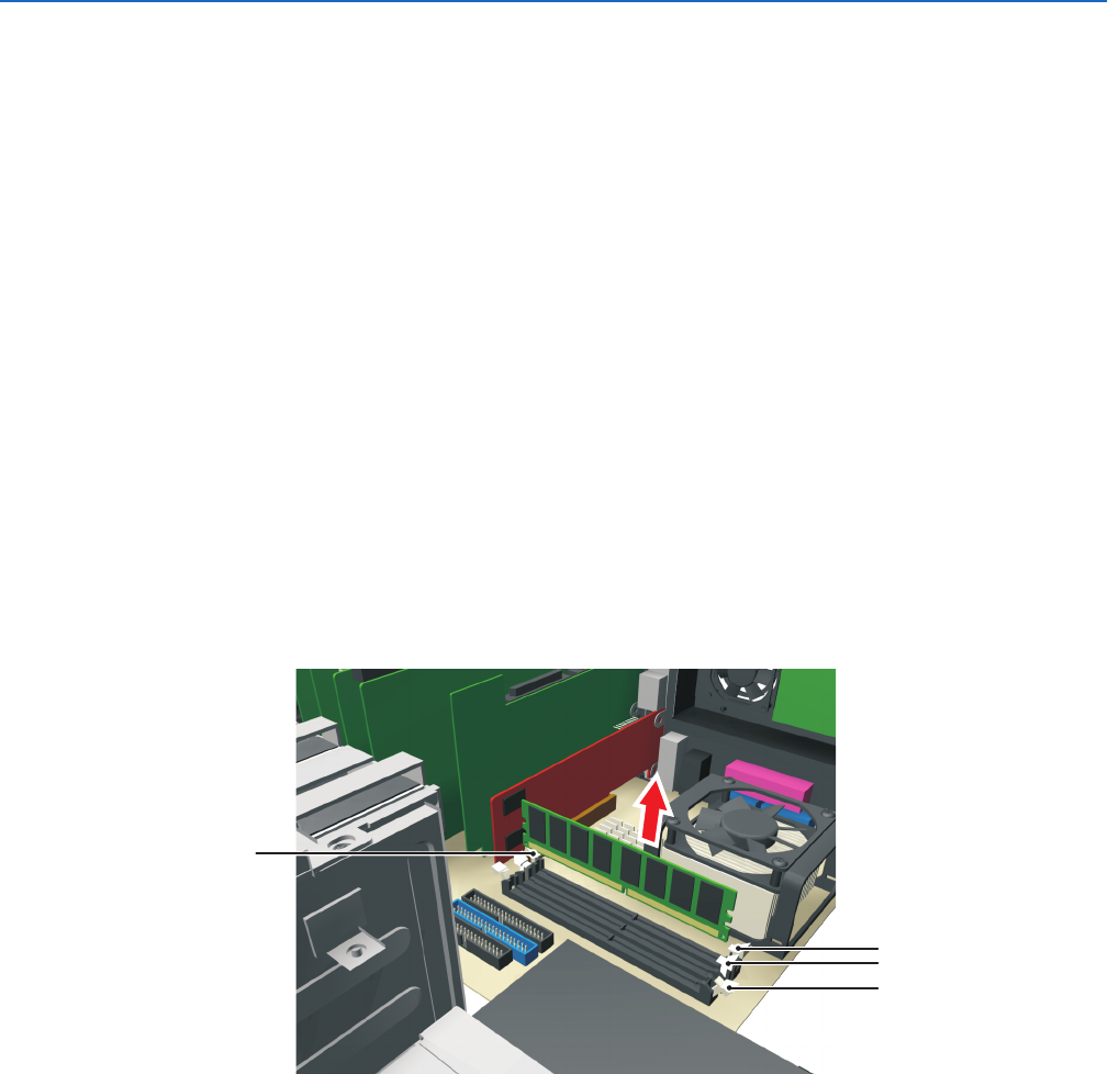
2. Remove the current 256 MB DIMM module from slot DIMM 1. Refer to Figure 7.
Figure 7.
Current 256 MB DIMM Module In DIMM 1
3. To re-install the current 256 MB DIMM module, do the following:
a. Align the current 256 MB DIMM module (removed from slot DIMM 1) with the socket for slot DIMM 2 so that the notch in the module
lines up properly with the break in the DIMM socket. Refer to Figure 8.
b. Make sure that the white retaining clips are not in the locked position by pressing outward and down on each clip.
CURRENT
256 MB DIMM
DIMM 1
DIMM 2
DIMM 3
 Manymanuals.com
 Manymanuals.de
 Manymanuals.fr
 Manymanuals.it
 Manymanuals.pl
 Manymanuals.cz
 Manymanuals.es
 Manymanuals-pt.com
Comments to this Manuals