Pelco Camclosure IP110 User Manual
Browse online or download User Manual for Security cameras Pelco Camclosure IP110. Pelco Camclosure IP110 User's Manual [en]
- Page / 44
- Table of contents
- TROUBLESHOOTING
- BOOKMARKS
- IP110 Series 1
- Camclosure 1
- Contents 3
- List of Illustrations 4
- List of Tables 5
- Important Safety Instructions 6
- Regulatory Notices 7
- Open Source Software Notice 8
- Description 9
- Basic System Configurations 10
- C3432M-G (4/09) 11 11
- BASIC SURFACE INSTALLATION 12
- C3432M-G (4/09) 13 13
- 404 PLASTER RING INSTALLATION 14
- SIDE CONDUIT INSTALLATION 15
- Wiring Tables 16
- ALARM AND 24 VAC WIRES 17
- CONNECTING ALARMS 18
- Camera Module 19
- MODULE INSTALLATION 20
- Camera Adjustments 21
- 22 C3432M-G (4/09) 22
- CENTER BUBBLE 23
- WITH LENS 23
- 0.125 INCH (3.175 mm) 23
- DN/CH SERIES ADJUSTMENTS 24
- SW4-4: Flickerless 25
- SW4-6: Reserved 25
- BLEMISH DETECTION 25
- DAY/NIGHT OPERATION 26
- SWITCH SETTINGS 27
- SW1-1: Video Format 27
- SW1-2: N/A 27
- SW1-5: Fluorescent/General 28
- SW1-7: Digital Slow Shutter 28
- AUTO IRIS LEVEL ADJUSTMENT 29
- Camera Positioning 30
- Install Dome and Trim Ring 31
- Service Connector 32
- C3432M-G (4/09) 33 33
- Reset Button 34
- Troubleshooting 35
- 36 C3432M-G (4/09) 36
- C3432M-G (4/09) 37 37
- Specifications 38
- ENVIRONMENTAL 39
- 40 C3432M-G (4/09) 40
- C3432M-G (4/09) 41 41
- REVISION HISTORY 42
- WARRANTY 43
Summary of Contents
INSTALLATIONC3432M-G (4/09) IP110 Series Camclosure®Integrated Camera System
10 C3432M-G (4/09)Basic System ConfigurationsFigure 2. Endura Network ExampleFigure 1. DHCP Network ExampleIMPORTANT NOTE. PLEASE READ. The network
Figure 4. Static Network ExampleFigure 3. Private Network ExampleC3432M-G (4/09) 11IP110IP110WEB BROWSERPRIVATE NETWORKNETWORK SWITCHIF NOT DHCP,
12 C3432M-G (4/09)Cover and Back Box InstallationThe IP110 Series Camclosure integrated camera system mounts only to a surface. It can be wired throu
C3432M-G (4/09) 134S ELECTRICAL BOX INSTALLATION1. Attach an ICS110-AP adapter plate (not supplied) to a 4S electrical box. Use two 8-32 x 0.75-inch
14 C3432M-G (4/09)404 PLASTER RING INSTALLATION1. Remove the two 8-32 x 0.375-inch Phillips pan head screws and washers (supplied) to separate the co
C3432M-G (4/09) 15SIDE CONDUIT INSTALLATION1. Remove the two 8-32 x 0.375-inch Phillips pan head screws and washers (supplied) to separate the cover
16 C3432M-G (4/09)Wiring TablesCAT5 CABLE Connect a Cat5 cable to the RJ-45 network connector. The 8-pin connector includes video and PoE for the cam
C3432M-G (4/09) 17ALARM AND 24 VAC WIRESCONNECTING A RELAY DEVICEThe IP110 Camclosure has an output for triggering an external device. It supports bo
18 C3432M-G (4/09)CONNECTING ALARMSThe IP110 Camclosure provides an alarm input for external signaling devices, such as door contacts or motion detec
C3432M-G (4/09) 19Camera ModuleThe IP110 Series Camclosure camera module includes the camera, camera bracket, and heater board. To perform most camer
20 C3432M-G (4/09)MODULE INSTALLATIONTo install the camera module into the back box:Figure 13. Back Box Connectors1. Plug the camera (10-pin), heate
C3432M-G (4/09) 21Camera AdjustmentsTo perform camera adjustments:1. Make sure the camera and service connectors are connected to the board inside th
22 C3432M-G (4/09)VARIFOCAL LENS ZOOM AND FOCUS ADJUSTMENTSNOTE: You will need a miniature Phillips or flat-tip screwdriver to loosen and tighten th
C3432M-G (4/09) 23To adjust the focus:1. Loosen the focus locking screw.2. Position the inverted dome approximately 0.125 inch (3.175 mm) from the fr
24 C3432M-G (4/09)DN/CH SERIES ADJUSTMENTSFigure 17. Adjusting the IP110-DN/CH Series CamclosureRefer to Figure 17 to adjust the IP110-DN or IP110-C
C3432M-G (4/09) 25SW4-4: FlickerlessIn certain lighting conditions, a flicker in the light source may affect camera operation. Flickering can be cau
26 C3432M-G (4/09)DAY/NIGHT OPERATIONNOTE: This section only applies to DN model cameras.DN model cameras regularly check the brightness level of th
C3432M-G (4/09) 27DW/CW SERIES (WIDE DYNAMIC RANGE) ADJUSTMENTSFigure 19. Adjusting the IP110-DW/CW Series CamclosureRefer to Figure 19 to adjust th
28 C3432M-G (4/09)SW1-4: Auto White Balance/Manual White BalanceAuto white balance (AWB) is enabled by default (ON).To manually set and lock the whi
Figure 20. DW Models Threshold Switching LevelsC3432M-G (4/09) 29Figure 18 and Table D show how the camera switches between color and black-white op
C3432M-G (4/09) 3ContentsImportant Safety Instructions. . . . . . . . . . . . . . . . . . . . . . . . . . . . . . . . . . . . . . . . . . . . . . . .
30 C3432M-G (4/09)Camera PositioningManually rotate and tilt the camera module to position the camera, and then tighten the tilt screws (axis 1 in F
C3432M-G (4/09) 31Install Dome and Trim RingFigure 22. Dome Liner Adjustment1. To adjust the dome liner (refer to Figure 22):a. Align the screw hole
32 C3432M-G (4/09)Service ConnectorFigure 23. S ervice ConnectorThe IP110 Series Camclosure integrated camera system includes a service connector th
Figure 24. Attaching the 2.5 mm Monaural Headphone PlugC3432M-G (4/09) 33d. Solder the center connector of the cable to the center pin of the plug.
34 C3432M-G (4/09)Reset ButtonUse the reset button located on the board inside the back box to access the following modes described in Table E.To acc
C3432M-G (4/09) 35TroubleshootingIf the following instructions fail to solve your problem, contact Pelco Product Support at 1-800-289-9100 (USA and C
36 C3432M-G (4/09)Image too light Installation error • Check DIP switch settings.• Use a service connector to check camera operation. Connect one end
C3432M-G (4/09) 37Network not working Faulty cable connectionCheck all cable connections and ensure all plugs are properly plugged in.Incorrect seria
38 C3432M-G (4/09)SpecificationsGENERALPan/Tilt Adjustment ManualPan 360°Tilt 80° (20° to 100° range) Rotation 360°Construction Aluminum with steel c
C3432M-G (4/09) 39VIDEOSignal System NTSC or PALCompression MPEG-4, MJPEG in Web viewing modeVideo Streams 3, simultaneousVideo Resolutions NTSC PA
4 C3432M-G (4/09)List of Illustrations1 DHCP Network Example. . . . . . . . . . . . . . . . . . . . . . . . . . . . . . . . . . . . . . . . . . . . .
40 C3432M-G (4/09)LENSType Varifocal with auto irisFocal Length 3.0~9.5 mm 9.0~22.0 mmFormat Size 1/3-inchOperationIris Auto (DC drive)Focus ManualZo
C3432M-G (4/09) 41
REVISION HISTORYManual # Date CommentsC3432M 3/07 Original version.C3432M-A 5/07 Cable harnesses modified per ECO 07-17470. Added picture elements t
PRODUCT WARRANTY AND RETURN INFORMATIONWARRANTYPelco will repair or replace, without charge, any merchandise proved defective in material or workmansh
Pelco, Inc. Worldwide Headquarters 3500 Pelco Way Clovis, California 93612 USAUSA & Canada Tel (800) 289-9100 Fax (800) 289-9150Internatio
C3432M-G (4/09) 5List of TablesA IP110 Series Models . . . . . . . . . . . . . . . . . . . . . . . . . . . . . . . . . . . . . . . . . . . . . . . .
6 C3432M-G (4/09)Important Safety Instructions1. Read these instructions.2. Keep these instructions.3. Heed all warnings.4. Follow all instructions.5
C3432M-G (4/09) 7Regulatory NoticesThis device complies with Part 15 of the FCC Rules. Operation is subject to the following two conditions: (1) this
8 C3432M-G (4/09)Open Source Software NoticeThis product includes certain open source or other software originated from third parties that is subject
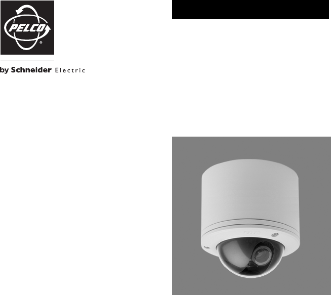
C3432M-G (4/09) 9DescriptionThe IP110 Series Camclosure® is an indoor/outdoor, fixed mini dome system with a built-in 100Base-TX network interface fo
Related products and manuals for Security cameras Pelco Camclosure IP110
 (12 pages)
(36 pages)
(56 pages)
(44 pages)
(44 pages)
(24 pages)
(13 pages)
(12 pages)
(12 pages)
(32 pages)
(24 pages)
(6 pages)
(32 pages)
(20 pages)
(20 pages)
(12 pages)
(36 pages)
(56 pages)
(44 pages)
(44 pages)
(24 pages)
(13 pages)
(12 pages)
(12 pages)
(32 pages)
(24 pages)
(6 pages)
(32 pages)
(20 pages)
(20 pages)
© 2020, manymanuals.com. All rights reserved. | 4.740 s |
 Manymanuals.com
 Manymanuals.de
 Manymanuals.fr
 Manymanuals.it
 Manymanuals.pl
 Manymanuals.cz
 Manymanuals.es
 Manymanuals-pt.com
Comments to this Manuals