Pelco pelco is110 User Manual
Browse online or download User Manual for Security cameras Pelco pelco is110. Pelco pelco is110 User's Manual
- Page / 36
- Table of contents
- BOOKMARKS
- IS110 Series 1
- Camclosure 1
- Contents 3
- List of Illustrations 4
- List of Tables 4
- Regulatory Notices 5
- Description 6
- PARTS LIST 7
- SHOWN ACTUAL SIZE 8
- UNSHIELDED TWISTED PAIR VIDEO 9
- BASIC SURFACE INSTALLATION 9
- 10 C3426M-E (3/09) 10
- C3426M-E (3/09) 11 11
- 404 PLASTER RING INSTALLATION 12
- C3426M-E (3/09) 13 13
- SIDE CONDUIT INSTALLATION 14
- C3426M-E (3/09) 15 15
- Camera Module 16
- (refer to Figure 7) 17
- Figure 7. Back Box Connectors 17
- CAMERA ORIENTATION 18
- MODULE INSTALLATION 18
- Camera Adjustments 19
- CENTER BUBBLE 20
- WITH LENS 20
- 0.125 INCH (3.175 mm) 20
- DN/CH SERIES ADJUSTMENTS 21
- AUTO IRIS LEVEL ADJUSTMENT 22
- VERTICAL PHASE ADJUSTMENT 23
- Adjusting Vertical Phase 23
- BLEMISH DETECTION 23
- DAY/NIGHT OPERATION 24
- SWITCH SETTINGS 25
- SW1-5: Fluorescent/General 26
- SW1-7: Digital Slow Shutter 26
- C3426M-E (3/09) 27 27
- Camera Positioning 29
- Install Liner and Trim Ring 30
- Service Connector 31
- 32 C3426M-E (3/09) 32
- Specifications 33
- CAMERA/LENS 34
- REVISION HISTORY 34
- WARRANTY 35
Summary of Contents
INSTALLATIONC3426M-E (3/09)IS110 SeriesCamclosure®Integrated Camera System
10 C3426M-E (3/09)8. Reinstall the back box inside the cover. For vandal-resistant installations, rotate the back box to position the conduit plug opp
C3426M-E (3/09) 116. Connect the power wires (refer to Table D).AC operation only: If you are wiring more than one Camclosure to the same transformer,
12 C3426M-E (3/09)404 PLASTER RING INSTALLATIONNOTE: You should install the camera module into the back box before installing the back box into the co
C3426M-E (3/09) 136. Reinstall the back box inside the cover. For vandal-resistant installations, rotate the back box to position the conduit plug opp
14 C3426M-E (3/09)SIDE CONDUIT INSTALLATIONNOTE: You should install the camera module into the back box before installing the back box into the cover.
C3426M-E (3/09) 158. Connect the video cable and wires:• BNC: Connect the BNC connector from the unit to a mating BNC connector.• UTP: Connect the blu
16 C3426M-E (3/09)Camera ModuleThe IS110 Series Camclosure camera module includes the camera, camera bracket, and heater board. To perform most camera
C3426M-E (3/09) 172. Unplug the camera (10-pin), service (3-pin), and heater board (4-pin) connectors from the back box (refer to Figure 7).Figure 7.
18 C3426M-E (3/09)CAMERA ORIENTATIONAt the factory, the camera module is configured for ceiling mounting. For wall mounting, you must change the camer
C3426M-E (3/09) 19Camera AdjustmentsTo perform the following camera adjustments, make sure to connect the camera and service connectors. You may have
20 C3426M-E (3/09)To adjust the focus:1. Loosen the focus locking screw.2. Position the inverted dome approximately 0.125 inch (3.175 mm) from the fro
C3426M-E (3/09) 21DN/CH SERIES ADJUSTMENTSRefer to Figure 11 to adjust the IS110-DN or IS110-CH model.Figure 11. Adjusting the IS110-DN/CH Series Camc
22 C3426M-E (3/09)SW4-4: FlickerlessIn certain lighting conditions, a flicker in the light source may affect camera operation. Flickering can be cause
C3426M-E (3/09) 23VERTICAL PHASE ADJUSTMENTUse this procedure for 24 VAC operation only.When using more than one camera power supply, a brief vertical
24 C3426M-E (3/09)DAY/NIGHT OPERATIONNOTE: This section only applies to DN model cameras.DN model cameras regularly check the brightness level of the
C3426M-E (3/09) 25DW/CW SERIES (WIDE DYNAMIC RANGE) ADJUSTMENTSRefer to Figure 13 to adjust the IS110-DW or IS110-CW model.Figure 13. Adjusting the IS
26 C3426M-E (3/09)SW1-4: Auto White Balance/Manual White BalanceAuto white balance (AWB) is enabled by default (ON).To manually set and lock the white
C3426M-E (3/09) 27SW1-8: Day/Night Operation (DW models only)NOTE: On CW models, SW1-8 is unused and does not affect camera operation.DW model cameras
28 C3426M-E (3/09)AUTO IRIS LEVEL ADJUSTMENTThe electronics of the IS110-DW and IS110-CW Series Camclosures automatically adjust the camera to the aut
C3426M-E (3/09) 29Camera PositioningRotate and tilt the camera module to position the camera. Then tighten the tilt screws (axis in Figure 15).NOTE:
C3426M-E (3/09) 3ContentsRegulatory Notices. . . . . . . . . . . . . . . . . . . . . . . . . . . . . . . . . . . . . . . . . . . . . . . . . . . . . .
30 C3426M-E (3/09)Install Liner and Trim Ring1. Adjust the liner (if installed), refer to Figure 16:a. Align the screw holes in the trim ring with tho
C3426M-E (3/09) 31Service ConnectorThe IS110 Series Camclosure integrated camera system includes a service connector that outputs camera video. Use it
32 C3426M-E (3/09)To assemble the cable:1. Attach the CPM 88 miniature coaxial connector to one end of the cable. Follow the directions supplied with
C3426M-E (3/09) 33SpecificationsGENERALPan/Tilt Adjustment ManualPan 360°Tilt 80° (20° to 100° range) Rotation 360°Construction Aluminum with steel ca
34 C3426M-E (3/09)CAMERA/LENSIf you need technical specifications for the camera itself, refer to the IS110 specification online at www.pelco.com.(Des
PRODUCT WARRANTY AND RETURN INFORMATIONWARRANTYPelco will repair or replace, without charge, any merchandise proved defective in material or workmansh
Pelco, Inc. Worldwide Headquarters 3500 Pelco Way Clovis, California 93612 USAUSA & Canada Tel (800) 289-9100 Fax (800) 289-9150Internatio
4 C3426M-E (3/09)List of Illustrations1 Package Components . . . . . . . . . . . . . . . . . . . . . . . . . . . . . . . . . . . . . . . . . . . . . .
C3426M-E (3/09) 5Regulatory NoticesThis device complies with Part 15 of the FCC Rules. Operation is subject to the following two conditions: (1) this
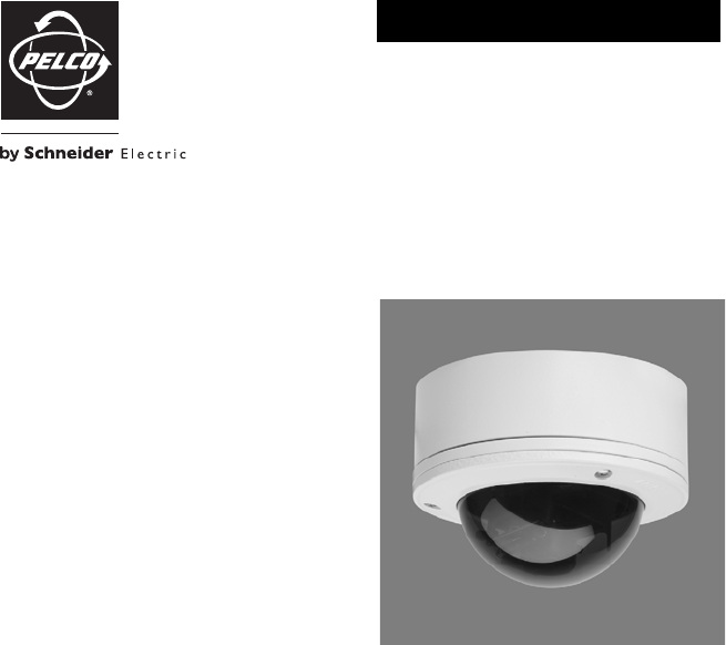
6 C3426M-E (3/09)DescriptionThe IS110 Series Camclosure® integrated camera system combines an environmental cover, back box, camera, lens, and lower d
C3426M-E (3/09) 7The IS111 models include the following specifications: Indoor/outdoor dome, vandal resistant, surface mount, clear bubble, liner, and
8 C3426M-E (3/09)Figure 1. Package ComponentsCOVER ANDBACK BOX 1 EA.CAMERA MODULE1 EA.TRIM RING, LINER,AND CLEAR BUBBLE1 EA.TRIM RING ANDSMOKED BUBBLE
C3426M-E (3/09) 9Cover and Back Box InstallationThe IS110 Series Camclosure integrated camera system mounts only to a surface. It can be wired through
Related products and manuals for Security cameras Pelco pelco is110
 (20 pages)
(32 pages)
(52 pages)
(66 pages)
(12 pages)
(12 pages)
(16 pages)
(24 pages)
(12 pages)
(40 pages)
(16 pages)
(16 pages)
(25 pages)
(20 pages)
(32 pages)
(52 pages)
(66 pages)
(12 pages)
(12 pages)
(16 pages)
(24 pages)
(12 pages)
(40 pages)
(16 pages)
(16 pages)
(25 pages)
© 2020, manymanuals.com. All rights reserved. | 1.838 s |
 Manymanuals.com
 Manymanuals.de
 Manymanuals.fr
 Manymanuals.it
 Manymanuals.pl
 Manymanuals.cz
 Manymanuals.es
 Manymanuals-pt.com
Comments to this Manuals