Pelco C3432M-F User Manual Page 11
- Page / 40
- Table of contents
- TROUBLESHOOTING
- BOOKMARKS
- IP110 Series 1
- Camclosure 1
- Contents 2
- List of Illustrations 3
- List of Tables 3
- Important Safety Instructions 4
- Regulatory Notices 5
- Open Source Software Notice 6
- Description 7
- Basic System Configurations 8
- NETWORK SWITCH 9
- NETMASK 255.255.0.0 9
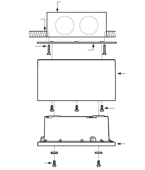
- BASIC SURFACE INSTALLATION 10
- C3432M-F (6/08) 11 11
- 404 PLASTER RING INSTALLATION 12
- SIDE CONDUIT INSTALLATION 13
- Wiring Tables 14
- ALARM AND 24 VAC WIRES 15
- Supervised Alarms 16
- CONNECTING ALARMS 16
- Unsupervised Alarms 17
- Alarm Connections 18
- Camera Module 19
- MODULE INSTALLATION 20
- Camera Adjustments 21
- 22 C3432M-F (6/08) 22
- DN/CH SERIES ADJUSTMENTS 23
- SW4-4: Flickerless 24
- SW4-6: Reserved 24
- BLEMISH DETECTION 24
- DAY/NIGHT OPERATION 25
- DEFAULT SWITCH POSITION 26
- SW1-5: Fluorescent/General 27
- SW1-7: Digital Slow Shutter 27
- AUTO IRIS LEVEL ADJUSTMENT 28
- Camera Positioning 29
- Install Dome and Trim Ring 30
- Service Connector 31
- 32 C3432M-F (6/08) 32
- Reset Button 33
- Troubleshooting 34
- C3432M-F (6/08) 35 35
- 36 C3432M-F (6/08) 36
- Specifications 37
- 38 C3432M-F (6/08) 38
- REVISION HISTORY 39
Related products and manuals for Security cameras Pelco C3432M-F
 (16 pages)
(25 pages)
(16 pages)
(16 pages)
(25 pages)
 (24 pages) (12 pages)
(12 pages)
(24 pages) (12 pages)
(12 pages)
 (50 pages)
(16 pages)
(96 pages)
(16 pages)
(44 pages)
(20 pages)
(61 pages)
(16 pages)
(50 pages)
(16 pages)
(96 pages)
(16 pages)
(44 pages)
(20 pages)
(61 pages)
(16 pages)
© 2020, manymanuals.com. All rights reserved. | 1.975 s |
 Manymanuals.com
 Manymanuals.de
 Manymanuals.fr
 Manymanuals.it
 Manymanuals.pl
 Manymanuals.cz
 Manymanuals.es
 Manymanuals-pt.com
Comments to this Manuals